The length of antenna you need to receive a radio signal is proportional to the signal’s wavelength, typically 1/2 or 1/4 of the wavelength. Cell phones operate at gigahertz frequencies, and so the antennas are small enough to hide inside the phone.
But AM radio stations operate at much lower frequencies. For example, there’s a local station, KPRC, that broadcasts at 950 kHz, roughly one megahertz. That means the wavelength of their carrier is around 300 meters. An antenna as long as a quarter of a wavelength would be roughly as long as a football field, and yet people listen to AM on portable radios. How is that possible?
There are two things going on. First, transmitting is very different than receiving in terms of power, and hence in terms of the need for efficiency. People are not transmitting AM signals from portable radios.
Second, the electrical length of an antenna can be longer than its physical length, i.e. an antenna can function as if it were longer than it actually is. When you tune into a radio station, you’re not physically making your antenna longer or shorter, but you’re adjusting electronic components that make it behave as if you were making it longer or shorter. In the case of an AM radio, the electrical length is orders of magnitude more than the physical length. Electrical length and physical length are closer together for transmitting antennas.
Here’s what a friend of mine, Rick Troth, said when I asked him about AM antennas.
If you pop open the case of a portable AM radio, you’ll see a “loop stick”. That’s the AM antenna. (FM broadcast on most portables uses a telescoping antenna.) The loop is tuned by two things: a ferrite core and the tuning capacitor. The core makes the coiled wiring of the antenna resonate close to AM broadcast frequencies. The “multi gang” variable capacitor coupled with the coil forms an LC circuit, for finer tuning. (Other capacitors in the “gang” tune other parts of the radio.) The loop is small, but is tuned for frequencies from 530KHz to 1.7MHz.
Loops are not new. When I was a kid, I took apart so many radios. Most of the older (tube type, and AM only) radios had a loop inside the back panel. Quite different from the loop stick, but similar electrical properties.
Car antennas don’t match the wavelengths for AM broadcast. Never have. That’s a case where matching matters less for receivers. (Probably matters more for satellite frequencies because they’re so weak.) Car antennas, whether whip from decades ago or embedded in the glass, probably match FM broadcast. (About 28 inches per side of a dipole, or a 28 inch quarter wave vertical.) But again, it does matter a little less for receive than for transmit.
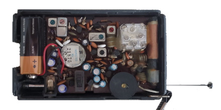
In the photo above, courtesy Rick, the AM antenna is the copper coil on the far right. The telescoping antenna outside the case extends to be much longer physically than the AM antenna, even though AM radio waves are two orders of magnitude longer than FM radio waves.
The reason why transmitting is different from receiving: you want a transmitting antenna to be *efficient*, but a receiving antenna can often be very inefficient and still do its job well.
If you connect an antenna system with 0.0001% efficiency to a transmitter that generates 1000 watts, then that means that 1 milliwatt goes out into the world as RF and 999.999 watts become heat somewhere in the antenna system. Usually this is considered a bad result, and for the sake of effective communication we want to keep transmit antenna efficiency high.
But if you connect an antenna system with 0.0001% efficiency to a receiver, which is 10km from a 1000-watt AM broadcast station, then that means that the antenna is delivering around a nanowatt (-60dBm) to the receiver rather than the milliwatt or so (0dBm) you could have gotten from a 100% efficient full-size antenna. A nanowatt is *plenty* of power for any decent receiver (it’s still considered a very strong signal), and an entire milliwatt is actually in the range where you have to start worrying about *damaging* the solid-state amplifiers that go into most radios these days.
An inefficient receive antenna reduces the strength of the signal that comes in, but it reduces the strength of any noise that’s received over the air as well, so the signal-to-noise ratio (which is what really matters) remains virtually unchanged by antenna efficiency as long as the “received noise” stays well above the noise generated in the receiver’s own electronics (including thermal noise). On frequencies below around 100MHz, this is almost always true, and down around 1MHz it’s very very true. When you get to higher frequencies where the naturally-occurring noise is less and the efficiency of amplifiers is also less, *then* you start worrying about getting enough signal strength to satisfy the receiver’s sensitivity.
The sensitivity of a good medium-wave receiver (the received signal strength at which the signal-to-noise ratio would start to degrade noticeably if there was no noise coming from the outside world) is around -120 to -110 dBm (1 to 10 femtowatts).
antennas can operate down to 0.1 lambda ( wavelength ) before degradation ( using an L to make it longer ).
a better question is: how does the antenna system for AM work with
a 2 inch ground ?( the metal power return inside the radio ) ?
( which might make as a dipole in creative thought )
The ferrite concentrates the received electromagnetic signal into a small physical area while also providing a form to rap the antenna windings. Ferrite is also a directional antenna and was used in radio direction finders such as the famous TransOceanic receivers.
The “coil” around the ferrite is not an antenna: it’s just an inductance (L).
You can connect that inductance in parallel with a capacitance (C) to conform a LC circuit. This circuit “resonates” at a given frequency (f=\frac{1}{2 \pi \sqrt{LC}}) , making the signal with this frequency stronger.
You can then connect a diode (that crops negative signal values) and a microphone (to transform current into sound) and you have a crystal radio that works even with a very small antenna, and without a battery! https://en.wikipedia.org/wiki/Crystal_radio
I thought that the sensitivity of the AM antenna was due to the ferrite bar at the core. A length of wire is picking up the electric field of the incident wave. The ferrite rod aerial is harvesting the magnetic component. Of course, it’s also resonant with the tuning capacitor, so that also enhances sensitivity.
Typo?
“the electrical length is orders of magnitude less than the physical length”
I think you mean more rather than less?
Thanks for the interesting article!
As a youth I constructed a minimal AM radio consisting of a chunk of germanium with a homemade mount and ‘catwhisker’ wire, an antenna the length of my back yard, and an earphone – no coil or capacitor required. I got excellent reception in Louisiana from a blues station in Tennessee. This was in the 50’s; I assume the radioverse is crowded enough now that this would no longer be feasible.
Oh, oh, I got one!
How come big objects (speakers, horns, kick-drums, …) are needed for reproducing bass?
But your ear-drums that hears it is tiny.
As efficiency isn’t the prime concern for a receiving aerial, you can just sample the E-field and have a broad band aerial that works from LF up to HF. No need for tuned circuits or anything. Amplifier needs to have very good intermodulation performance.
https://owenduffy.net/antenna/PA0RDT-MiniWhip/
I recalled 1 of Paul Nahin’s book talks about the science of radio.
https://www.amazon.com/Science-Radio-Electronics-Workbench-Demonstrations/dp/0387951504/
I don’t think there’s any fundamental reason why you can’t make a very small AM transmitting antenna that’s reasonably efficient, but it requires special engineering. Magnetic Loop transmit antennas exist for shortwave, and there are designs for compact “E-M” antennas for transmitting. They create the Electric field and the Magnetic field in separate small antennas, and they combine to form a radio wave at a long distance from the antennas.
@Jim Theriot.
You still can hear a lot of stations at night on an AM radio.
When I was delivering copies of -The Detroit Free Press- 40 years ago, I was listening to WWL on my route.
I was an electronics teacher at the Naval Training Center at Great Lakes and taught am radio circuitry to the Navy. I wanted to clear up that the tunable capacitor does not change the effective length of the antenna. The antenna is actually a loop antenna that can be as small as 1/100th wavelength in it’s coiled form. The reception is based on the area but the important thing to take away is that the antenna is self contained and is a very wide band antenna type. No, it’s not very efficient but the advantage is that the noise isn’t picked up that well either. So, you just amplify the signal more and your good to go.
The antenna simultaneously recieves the entire am band and then sends that jumbled signal to the selector (or tuner). This is where that capacitor comes in. It is in parallel with a different coil inductor. As the frequency increases, an inductors reactance goes up. As the frequency decreases, the reactance of the capacitor goes up. Where the reactances are the same, that frequency is boosted and the other frequencies are diminished. As you change the value of the tuning capacitor, that frequency changes. That’s how you pick out a specific channel out of the big jumble.
Hope that helps.
Transmitting antenna performance is about efficiency: for a given input power, maximizing the portion radiated in the desired direction(s) while minimizing the portion wasted as heat. There is no reason for a transmitting antenna to be resonant other than it simplifies impedance matching for efficient transfer of power.
Receiving antenna performance is about signal to noise ratio: in the lower HF and medium wave frequencies the S/N is dominated by external noise sources and the electronic noise in the receiver is insignificant. So a short antenna is sufficient—for general purpose receiving. AM broadcasters transmit with high power to overcome the environmental noise, and a longer antenna would pick up more signal but also more noise so a longer antenna has no significant advantage for receiving at these low frequencies, unless it is a long antenna configured to provided some desired directivity which again, is not about increasing signal strength but rather signal to noise ratio.
There is a very important factor that no one has mentioned here and that is Q Factor, or Quality Factor, which effectively describes th eproperty of the tuned circuit related to dampening or bandspread.
In the anology of the childs swing with solid metal “arms” (as opposed to chains), if there was no hinge fricyion and no windage the swing would go forever at the same amplitude once set in motion.
But every swing some losses are incurred and the amplitude dies down, if not topped up by any pushes.
The same goes for a tuned circuit (coil and capacitor), except resistance is a key fator in losses.
The ferrite loopstick in an AM radio allows the tuned circuit to have many less turns than an air cored inductor for the same frequency so there fore the resistive losses are less (less wire) and the Q factor is higher and the resonant peak at the tuned point is higher.
Maximising coil Q is one big factor how DX crystal set listeners can get 1000, sometimes 2000 km range to pick up AM station on an unpowered crystal set.
Now before I get a bunch of replies about all sorts of things like skin effect, litz wide, copper tube coils and what ever, this is only a very basic explanation, if you need to know more you need to go to the textsbooks.