Why determinants with columns of ones?

Geometric equations often involve a determinant with a column of 1s. For example, the equation of a line through two points:

\begin{vmatrix} x & y & 1 \\ x_1 & y_1 & 1 \\ x_2 & y_2 & 1 \\ \end{vmatrix} = 0

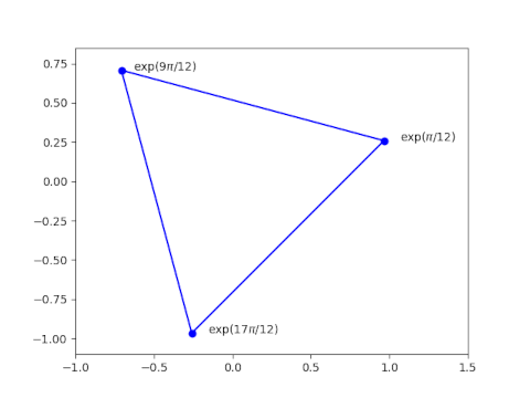
The equation of a circle through three points:

\begin{vmatrix} x^2 + y^2 & x & y & 1 \\ x_1^2 + y_1^2 & x_1 & y_1 & 1 \\ x_2^2 + y_2^2 & x_2 & y_2 & 1 \\ x_3^2 + y_3^2 & x_3 & y_3 & 1 \\ \end{vmatrix} = 0

The equation of a general conic section through five points

\begin{vmatrix} x^2 & xy & y^2 & x & y & 1 \\ x_1^2 & x_1 y_1 & y_1^2 & x_1 & y_1 & 1 \\ x_2^2 & x_2 y_2 & y_2^2 & x_2 & y_2 & 1 \\ x_3^2 & x_3 y_3 & y_3^2 & x_3 & y_3 & 1 \\ x_4^2 & x_4 y_4 & y_4^2 & x_4 & y_4 & 1 \\ x_5^2 & x_5 y_5 & y_5^2 & x_5 & y_5 & 1 \\ \end{vmatrix} = 0

The equation of a Mobius (bilinear) transformation sending z1, z2, and z3 to w1, w2, and w3:

\begin{vmatrix} 
z & w & zw  & 1\\
z_1 & w_1 & z_1w_1 & 1 \\
z_2 & w_2 & z_2w_2 & 1 \\
z_3 & w_3 & z_3w_3 & 1 \\ 
\end{vmatrix} = 0

Why all the determinants and why all the 1s?

When you see a determinant equal to zero, you immediately think of matrix rows or columns being linearly dependent. But in the examples above it isn’t the Cartesian coordinates that are linearly dependent but projective coordinates that are dependent.

The 1s are in the last column, though they need not be, as a clue as to where they came from. You could permute the rows and columns any way you like and the determinant would still be zero. The 1s are in the last column because you can take Cartesian coordinates into projective coordinates by adding a 1 at the end.

This 1 is sort of a silent partner, and can be ignored much of the time. But the last projective coordinate is critical when it’s necessary to be rigorous about points at infinity. The examples above are interesting because they are an application of homogeneous coordinates when there’s no concern about points at infinity.

Related posts

Conformal map of rectangle to ellipse

The previous post looked at what the sine function does to circles in the complex plane. This post will look at what it does to an rectangle.

The sine function takes a rectangle of the form [0, 2π] × [0, q] to an ellipse with semi major axis cosh(q) and semi minor axis sinh(q).

The image of horizontal lines

is a set of concentric ellipses.

The sine function almost maps the interior of the rectangle to the interior of the ellipse.

If we add vertical lines to the rectangle

the results are a little puzzling.

The images of the dashed green vertical lines seem broken in the ellipse. Their images above the real axis don’t line up with their images below the real axis. This isn’t easy to see on the edges, but you can see it in the middle. There are 20 green lines in the preimage but 19 in the image. That’s because sine maps both vertical edges of the rectangle to the same line segment in the image.

It will be clearer if we make our rectangle slightly narrower, changing the base from [0, 2π] to [0, 6].

Now notice the split in the image;

Now we can see what’s going on. Sine doesn’t distort the rectangle into an ellipse from the inside out, not like the map between a circle and an ellipse. Instead it maps the left edge of the rectangle along the imaginary axis, then bends the rectangle around the real axis clockwise, then back around the real axis.

So sine conformally maps the interior of the rectangle, the open rectangle (0, 2π) × (0, q) to the interior of the ellipse with a couple slits removed, one slit along the positive imaginary axis and another slit along the real axis from −1 to 1.

So how would you map the interior of a rectangle to the interior of an ellipse with no slits? For the special case of a square, you could compose the maps from two previous posts: map the square to a disk, then map the disk to an ellipse.

Related posts

Sine of a circle

What does it look like when you take the sine of a circle? Not the angle of points on a circle, but the circle itself as a set of points in the complex plane?

Here’s a plot for the sine of circles of radius r centered at the origin, 0 < r < π/2.

Here’s the same plot but for π/2 < r < π.

Now let’s see what happens when we shift the center of the circle over by 1, first for 0 < r < π/2.

And now for π/2 < r < π.

Here’s the Python code that produced the first plot; the code for the other plots is very similar.

    import matplotlib.pyplot as plt
    from numpy import pi, exp, sin, linspace

    t = linspace(0, 2*pi, 500)

    for r in linspace(0.1, pi/2, 17):
        z = r*exp(1j*t) 
        w = sin(z)
        plt.plot(w.real, w.imag, 'b')

    plt.gca().set_aspect("equal")
    plt.title("$\sin(r\exp(it))$, $0 < r < \pi/2$")
    plt.show()

Related posts

Test whether three complex numbers are vertices of an equilateral triangle

Let a, b, and c be three complex numbers.

Triangle with vertices at exp(pi/12), exp(9pi/12), and exp(17pi/12).

These numbers form the vertices of an equilateral triangle in the complex plane if and only if

\left| \begin{matrix} a & b & 1 \\ b & c & 1 \\ c & a & 1 \\ \end{matrix} \right| = 0

This theorem can be found in [1].

If we rotate the matrix above, we multiply its sign by −1. If we then swap two rows we multiply the determinant again by −1. So we could write the criterion above with the 1’s on the top row.

\left| \begin{matrix} 1 & 1 & 1 \\ a & b & c \\ b & c & a \\ \end{matrix} \right| = 0

See also this post which gives the area of a triangle in the complex plane, also in terms of a determinant.

[1] Richard Deaux. Introduction to the Geometry of Complex Numbers.

Arbitrary precision math in gawk

The idea of using awk for any math beyond basic arithmetic is kinda strange, and yet it has some nice features.

Awk was designed for file munging, a task it does well with compact syntax. GNU awk (gawk) supports the original minimalist version of awk and adds more features. It supports arbitrary precision arithmetic by wrapping the GMP and MPFR libraries. (When I refer to “awk” in this post I mean the features common to awk and gawk.)

If you just want extended precision, it would be easier to use bc. But if you’ve written an awk script and want to do some extended precision calculation in place rather than in a different tool, you could take advantage of gawk’s extension.

Here’s a one-liner to compute π to 100 decimal places using gawk.

    gawk -M -v PREC=333 'BEGIN {printf("%0.100f\n", 4*atan2(1,1))}'

The -M flag tells gawk to use arbitrary precision arithmetic.

NB: Your version of gawk may not support arbitrary precision. If so, running the code above will give the following warning:

    gawk: warning: -M ignored: MPFR/GMP support not compiled in

The -v flag tells gawk you’re about to set a variable, namely PREC variable for precision. You could set PREC in the body of your code instead.

Precision is measured in bits, not digits, and so for 100 digits we require 333 bits [1].

Awk is line-oriented. There’s an implicit loop around an awk program that loops over every line of input files. But you can specify code to run before the loop in a BEGIN block, and code to run after the loop in an END block. Here we just need the BEGIN block, no loop and no END.

We compute π as 4 times the arctangent of 1. Awk has an atan2 function rather than a atan function. The function atan(z) returns an angle between -π/2 and π/2 whose tangent is z. The function atan2(y, x) returns an angle between -π and π, in the same quadrant as x and y, whose tangent is y/x. The atan2 function is more general than atan since atan(z) equals atan2(z, 1). This is one advantage gawk has over bc, since bc has only an atan function (which it calls a).

***

[1] Where did 333 bits come from? It’s log2 10100, rounded up to the next integer. You could compute the logarithm in awk using

    awk 'BEGIN {print 100*log(10)/log(2)}'

Note that this uses awk; you don’t need gawk for this calculation. Awk doesn’t have a function to compute log base 2, only natural logs. So you use the fact that

log2(x) = log(x)/log(2).

Unicode arrows: math versus emoji

I used the character ↔︎︎ (U+2194) in a blog post recently and once again got bit by the giant pawn problem. That’s my name for when a character intended to be rendered as text is surprisingly rendered as an emoji. I saw

f (emoji <->) f dx dy dz

when what I intended was

f <-> f dx dy dz

I ran into the same problem a while back in my post on modal logic and security. The page contained

when I intended

This example is more surprising because → (U+2192) is rendered as text while ↔︎ (U+2194) is rendered as an image. This seems capricious. Why are some symbols rendered as text while other closely-related symbols are not? The reason is that some symbols are interpreted as emoji and some are not. You can find a full list of text characters that might be hijacked as emoji here.

One way to fix this problem is to use the Unicode “variation selector” U+FE0E to tell browsers that you’d like your character interpreted as text. You can also use the variation selector U+FE0F if you really do want a character displayed as an emoji. See this post for details.

(I use U+FE0E several times in this post. Hopefully your browser or RSS reader is rendering it correctly. If it isn’t, please let me know.)

Update: This post looks terrible in the RSS reader on my phone because the reader ignores the variation selectors. See the comments for a screenshot. It renders as intended in my browser, desktop or mobile.

It’s not always convenient or even possible to use variation selectors, and in that case you can simply use different symbols.

Here are four Alternatives to ↔︎ (U+2194):

  • ⟷ (U+27F7)
  • ⇔ (U+21D4)
  • ⟺ (U+27FA)
  • ⇆ (U+21C6)

There is no risk of these characters being interpreted as emoji, and their intent may be clearer. In the two examples above, I used a double-headed arrow to mean two different things.

In the first example I wanted to convey that the Hodge operator takes the left side to the right and the right side to the left. Maybe ⇆ (U+21C6) would have been a better choice. In the second example, maybe it would have been clearer if I had used ⇒ (U+21D2) and ⇔ (U+21D4) rather than → (U+2192) and ↔︎ (U+2194).

Another math symbol that is unfortunately turned into an emoji is ↪︎ (U+21AA). In TeX this is \hookrightarrow. I used this symbol quite a bit in grad school to indicate that one space embeds in another. I don’t know of a good alternative to this one. You could use ⤷ (U+2937), though this looks kinda odd.

The Orange Book

I was spelunking around in Unicode and saw that there’s an emoji for orange book, U+1F4D9.

Orange Book emoji Linux

As is often the case, the emoji renders differently in different contexts. The image above is from my Linux desktop and the image below is from my Macbook. I tried created an image on my Windows box but it didn’t have a glyph for this character.

Orange book emoji Apple

When I saw “orange book” my first thought was the US Department of Defense publication Trusted Computer System Evaluation Criteria (TCSEC), aka DoDD 5200.28-STD, commonly know in security circles as the Orange Book. For a split second I thought “Is this book so famous that there’s an emoji for it?!” But of course that’s not the case.

There are emoji for several colors of books, and there are several books in the DOD “Rainbow Series” publications. such as the Green Book for password management. (There’s also an emoji for green book: U+1F4D7).

TCSEC

So what is The Orange Book? Here’s a photo of the cover.

Department of Defense Trusted Computer System Evaluation Criteria

Here’s how Bruce Schneier describes the book in Applied Cryptography.

The NCSC publishes the infamous “Orange Book.” It’s actual title is the Department of Defense Trusted Computer System Evaluation Criteria, but that’s a mouthful to say and the book has an orange cover. The Orange Book attempts to define security requirements, gives computer manufacturers an objective way to measure the security of their systems, and guides them as to what to build into their secure products. It focuses on computer security and doesn’t really say a lot about cryptography.

The Orange Book is now deprecated in favor of The Common Criteria for Information Technology Security Evaluation, ISO/IEC 15408.

Related posts

What does rotating a matrix do to its determinant?

This post will look at rotating a matrix 90° and what that does to the determinant. This post was motivated by the previous post. There I quoted a paper that had a determinant with 1s in the right column. I debated rotating the matrix so that the 1s would be along the top because that seems more natural, but in the end I kept the original notation. If I had rotated the matrix, I’d need to adjust the value of the determinant.

Rotating a matrix is a an unusual operation. When someone speaks of turning a matrix over, they usually mean taking the transpose; taking the transpose is a reflection, not a rotation. And when you see the words “rotation” and “matrix” in close proximity, the topic is a matrix that represents a rotation. That’s not what this post is about: the matrix isn’t performing a rotation; a rotation is being performed on it.

Here’s an example:

\begin{pmatrix} a & b & c \\ d & e & f \\ g & h & i \end{pmatrix} \rightarrow \begin{pmatrix} c & f & i \\ b & e & h \\ a & d & g \end{pmatrix}

Using subscripts makes the example above a little harder to read but much easier to formalize.

\begin{pmatrix} a_{11} & a_{12} & a_{13} \\ a_{21} & a_{22} & a_{23} \\ a_{31} & a_{32} & a_{33} \end{pmatrix} \rightarrow \begin{pmatrix} a_{13} & a_{23} & a_{33} \\ a_{12} & a_{22} & a_{32} \\ a_{11} & a_{21} & a_{31} \end{pmatrix}

If we denote a matrix by A and its image after rotation as A‘, then the components a‘ of A‘ are related to the components a of A by

a'_{ij} = a_{j, n-i+1}

To form the rotation of A, we take the transpose of A, then reverse the order of the rows. In matrix notation,

A' = JA^T

where J is the matrix that has 1’s on the secondary diagonal, the diagonal running southwest to northeast, and 0’s everywhere else. The matrix J is the rotation of the identity matrix I.

The determinant of A‘ is the determinant of J times the determinant of AT, and the determinant of AT is the same as the determinant of A.

\det A' = \det J \det A^T = \det J \det A

So the last thing we need to do to compute the determinant of A‘ is to compute the determinant of J.

We can turn I into J, and vice versa, by reversing the order of the rows. Let’s do this one pair of rows at a time. We swap the first and last rows. Then we swap the second row with the second to last row, then swap the third row from the top with the third row from the bottom, etc.

Suppose I is an n × n matrix, and first assume n is even. Then we need to do n/2 swaps, swapping each of the top n/2 rows with one of the bottom n/2 rows. Each swap reverses the sign of the determinant, and so the determinant of J is (−1)n/2. Now if n is odd, the middle row doesn’t move. So we swap the top (n − 1)/2 rows with the bottom (n − 1)/2 rows. So in that case the determinant of J is (−1)(n−1)/2. We can combine the even and the odd case using floor notation:

\det A' = (-1)^{\lfloor n/2\rfloor} \det A

Area of a triangle in the complex plane

I recently ran across an elegant equation for the area of a triangle in the complex plane with vertices at z1, z2, and z3. [1].

A(z_1, z_2, z_3) = \frac{i}{4} \, \left| \begin{matrix} z_1 & \bar{z}_1 & 1 \\ z_2 & \bar{z}_2 & 1 \\ z_3 & \bar{z}_3 & 1 \\ \end{matrix} \right|

This formula gives the signed area: the area is positive if the points are given in countclockwise order and negative otherwise.

I’ll illustrate the formula with a little Python code. Let’s generate a random triangle.

    import numpy as np

    np.random.seed(20221204)
    r = 100*np.random.random(6)
    z1 = r[0] + 1j*r[1]
    z2 = r[2] + 1j*r[3]
    z3 = r[4] + 1j*r[5]

Here’s what our triangle looks like plotted.

Now let’s calculate the area using the formula above and using Heron’s formula.

    
    def area_det(z1, z2, z3):
        det = 0
        det += z2*z3.conjugate() - z3*z2.conjugate()
        det -= z1*z3.conjugate() - z3*z1.conjugate()
        det += z1*z2.conjugate() - z2*z1.conjugate()
        return 0.25j*det
    
    def area_heron(z1, z2, z3):
        a = abs(z1-z2)
        b = abs(z2-z3)
        c = abs(z3-z1)
        s = 0.5*(a + b + c)
        return np.sqrt(s*(s-a)*(s-b)*(s-c))
        
    print(area_heron(z1, z2, z3))
    print(area_det(z1, z2, z3))

This prints -209.728 and 209.728. The determinate gives a negative area because it was given the points in clockwise order.

[1] Philip J. Davis. Triangle Formulas in the Complex Plane. Mathematics of Computation. January 1964.

Finding a vector potential whose curl is given

The previous post showed that if a vector field F over a simply connected domain has zero curl, then there is a potential function φ whose gradient is F.

An analogous result says that if the vector field F has zero divergence, again over a simply connected domain, then there is a vector potential Φ whose curl is F.

These are both special cases of Poincaré’s lemma.

This post will outline how to calculate Φ. First of all, Φ is far from unique. Any vector field with zero curl can be added to Φ without changing its curl. So if

Φ = (Φ1, Φ2, Φ3)

then we can assume that one of the components, say Φ3, is zero by adding the right curl-free component. If you find that argument less than convincing, look at it this way: we’re going to solve a harder problem than simply find Φ such that ∇×Φ = F by giving ourselves the additional requirement that the last component of Φ must be zero.

Now if Φ = (Φ1, Φ2, 0) and ∇×Φ = F, then

−∂z Φ2= F1
z Φ1 = F2
x Φ2 − ∂y Φ1 = F3

We can solve the first equation by integrating F1 with respect to z and adding a function of x and y to be determined later. We can solve the second equation similarly, then use the third equation to determine the functions of x and y left over from solving the first two equations.

***

This post is the third, and probably last, in a series of posts looking at vector calculus from a more advanced perspective.  The first post in the series looked at applying {grad, curl, div} to {grad, curl, div}: seeing which combinations are defined, and which combinations are always 0. To illustrate the general pattern, the post dips into differential forms and the Hodge star operator.

The second post looked at finding the (scalar) potential function for a curl-free vector field, and mentions connections to topology and differential equations.

The present post is a little terse, but it makes more sense if you’ve gone through the previous post. The method of solution here is analogous to the method in the previous post, and that post goes into a little more detail.